CLOSURES FOR GLASS CONTAINERS
The glass package commonly used for low-acid and acidified foods
is comprised of two separate elements- the glass container and
the metal closure. Both are essential for forming a proper hermetic
seal. The characteristics of the glass container and closure (also
referred to as cap or lid) will be discussed in this chapter along
with the methods for evaluating the closure application.
The Basic
Parts of a Glass Container
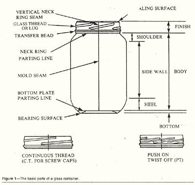
The three basic parts of
a glass container are the finish, the body and the bottom (Figure
1).
These
are formed by the three parts of the glass container molds in
which they are made.
FINISH--The finish is the part of the
jar that holds the cap or closure, the glass surrounding the
opening in the container. In the manufacturing process, it is
made in the neck ring or the finish ring. It is so named because,
in early hand glass manufacturing, it was the last part of the
glass container to be made, hence the term "finish"
BODY----The body of the
container is the portion that is made in the body-mold. It is,
in most cases the largest part of the container and lies between
the finish and the bottom.
BOTTOM--The bottom of the
container is made in the bottom plate part of the glass-container
mold.
THE FINISH
The finish of glass containers
has several specific areas, as follows
(Figure 1):
SEALING SURFACE---
The portion of the finish that makes contact with the sealing
gasket or liner. The sealing surface is usually on the top of
the finish, but may be a combination of the both top and side
seal.
Glass Thread or Lug---One
of several horizontal, tapering and protruding ridges of glass
around the periphery of the finish that permit specially-designed
edges or lugs on the closure to slide between these protrusions
and fasten the closure to securely with a partial turn. The
number of lugs on the closure and their precise configuration
is established by the closure manufacturer.
CONTINUOUS THREAD--A continuous
spiral projecting glass ridge on the finish of a container intended
to mesh with the thread of a screw-type closure.
TRANSFER BEAD--a continuous
horizontal ridge of glass near the bottom of the finish used
in transferring of container from one part of the manufacturing
operation to another.
Note: Not all glass containers
have transfer beads. Some achieve the transfer in manufacturing
through different means.
VERTICAL NECK RING SEAM--a
mark on the glass finish resulting from the joint of matching
the two parts of the neck ring, also referred to as the Mold
Match or Parting Line.
NECK RING PARTING LINE---A
horizontal mark on the glass surface at the bottom of the neck
or finish ring resulting from the matching of the neck ring
parts with the body-mold parts.
THE BODY
The characteristic parts of the
body of a glass container are shown in
Figure1:
SHOULDER--The portion
of a glass container in which the maximum cross-section of the
body area decreases to join the neck or finish area. The neck
area is not shown in Figure 1 because most glass container
for processed goods have very little neck. Actually, the neck
would be any straight area between the shoulder and the bottom
of the bead or, with beadless finishes, the neck ring parting
line.
HEEL--The
heel is the curved portion between the bottom and the beginning
of the straight area of the side wall
SIDE WALL-- The remainder
of the body area between the shoulder and the heel.
MOLD SEAM--A vertical mark
on the glass surface in the body area resulting from matching
the two parts of the body-mold. The body-mold seam may or may
not align with the vertical neck ring seam.
THE BOTTOM
BOTTOM
PLATE PARTING LINE--A
horizontal mark on the glass surface resulting from the matching
of the body-mold parts with the bottom plate.
BEARING SURFACE--The portion
of the container on which it rests. The bearing surface may
have a special configuration known as the stacking feature,
which is designed to provide some interlocking of the bottom
of the jar with the closure of another jar on which it might
be stacked for display purpose.
DISCUSSION
OF THE FINISH
Many different finishes exist
for closing glass containers. Figure 1 shows only three general types, which may be varied
for use with specific closures.
Every type of closure for sealing
glass containers has a specific glass finish with which the
closure has been designed to function. Attempts to put a lug
cap on a jar with a Press-on Twist-off (PT) finish would be
futile. Several different types of lug closures are available,
each of which has been designed to work best with a specific
lug-style finish.
Fortunately, many glass finishes are standardized. For
every finish standard designation, a specific set of dimensions,
specifications and tolerances have been established by the Glass
Packaging Institute, a trade association that works with glass
manufacturers and closure manufacturers. Each finish standard
drawing has a specific number and may be obtained directly from
the Glass Packaging Institute or through the glass manufacturer.
LUBRICANTS
OR GLASS SURFACE TREATMENTS
Surface treatments or lubricants
on glass containers serve the beneficial purpose of easing the
smooth flow of containers through conveying systems. They protect the outside surface of the container
from abrasion during manufacture and distribution. Many different
treatments are used. The use
of or change in a surface treatment should be fully discussed
with both the glass container and closure suppliers to prevent
potential problems. For example, excess surface treatment may
effect closure performance or label application.
DEFINITIONS
OF TERMS FOR GLASS CLOSURES
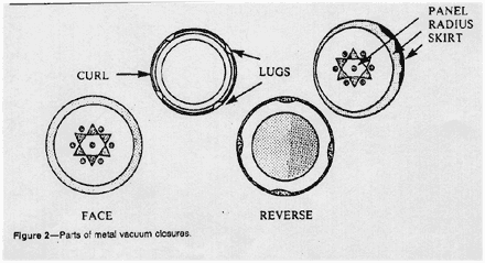
Among the terms commonly used for describing parts of metal
vacuum closures are the following
(Figure 2):
PANEL-- The flat center area in
the top of the cap.
RADIUS or SHOULDER--
The rounded area at the outer edge of the panel connecting the
panel and skirt.
SKIRT--The flat, nearly vertical
portion on the side of the cap. The skirt may be smooth, knurled
or fluted and serves as the gripping surface.
CURL- The round or rolled portion
at the bottom of the skirt that adds rigidity to the cap and
serves to protect the cut edge of the metal.
LUG--A horizontal inward protrusion
from the curl that is seated under the thread on the glass finish
and holds the cap in position.
THREAD--The spiral groove on the
skirt of a continuous thread closure that meshes with the tread
on the glass finish.
FACE-- The outside of the cap.
REVERSE-- The inside of the cap.
COATINGS and LITHOGRAPHY-- Coatings
and inks that are used on the inner and outer surfaces of the
cap to protect the metal from attack, adhere gasket materials
and decorate the closure.
GASKET--The actual sealing member
of the cap that must make intimate contact with the glass finish
at the proper point to form an effective seal. Gaskets may be
made from plastisol compounds.
PLASTISOLS--Suspensions of finely
divided resin in a plasticizer, which are usually of two types:
(1) flowed in--used in the standard lug or twist cap, and (2)
molded-used in the PT cap. Plastisols are tailored to the product
and process. For example, a closure intended for sealing a pasteurized
product may not be suitable on a retorted product.
SAFETY BUTTON or FLIP PANEL--A raised,
circular area in the center of the panel that is used only for
vacuum packed products and serves two principal purposes:
1. Dud detection--In the packaging plant it aids in automatic
on-line detection of low-vacuum or no-vacuum packages.
2. Consumer indicator-It is an indicator to the
consumer that the package is properly sealed when opened in
the home. In addition to visual evidence of a disrupted seal,
there is also an audible signal.
ROLE
OF VACUUM IN OBTAINING GOOD SEALS
Almost all low-acid and acidified
foods packed in glass containers are sealed with vacuum-type
closures. The following discussion deals exclusively with
this type of closure. The vacuum within the package and the
resultant positive pressure on the outside of the cap play an
important role in forming and maintaining a good seal. It is
important to know how vacuum is formed, what may affect the
vacuum level, and how, when, and where it should be measured.
VACUUM
CAPPERS for GLASS CONTAINERS
Two basic types of cappers apply
caps while forming a vacuum in the container--the mechanical
vacuum capper and the stream-flow capper. The mechanical vacuum
capper is used primarily on dry products and applies the cap
to the jar in an evacuated chamber. It is rarely used on low-acid
processed foods.
In stream-flow cappers, either straight line or rotary the container
is subjected to a controlled stream atmosphere that displaces
the headspace gases from the jar by a flushing action. The stream
is trapped in the headspace as the cap is applied, then condenses
to form a vacuum that helps hold the closure in place. As a
aid to good sealing, the gasket in Plastisols-lined caps is
softened by stream.
FACTORS
AFFECTING VACUUM FORMATION
Four primary factors affect vacuum formation:
1. Headspace is an important
factor in efficient sealing, particularly in stream-flow cappers.
For low-acid food products, sufficient headspace must be allowed
to trap adequate stream in the container for forming a vacuum
and to accommodate product expansion during retorting. The correct
amount of headspace varies with product, processes and product
design However, a rule-of-thumb indicator is that the headspace
should be not less than 6 percent of the container volume when
measured at the capping temperature. Inadequate headspace can
result in displacement of deformation of the closure during
retorting. This 6 percent headspace is not as critical with
acidified products that are either hot-filled or pasteurized.
There still has to be sufficient headspace, however, to allow
for vacuum formation, a clean fill and some product expansion
during pasteurization.
2. Product sealing temperature affects
the final vacuum obtained due to the effect of product contraction
upon cooling. Other factors being constant, the higher the product
temperature at the time of sealing, the higher the final package
vacuum. Product temperature may also affect the final vacuum
by its interaction with the amount of air in the product. Usually,
higher filling temperatures result in less air in the product.
3. Air in the product, as
mentioned above, can have a direct effect on the final package
vacuum and should be kept at a minimum for good sealing, product
quality and product appearance. The more air that is trapped
in the product, the lower the vacuum.
4. Capper vacuum efficiency refers
to the ability of the capper to produce vacuum in sealed containers.
The most convenient, routine check on the vacuum efficiency
of a stream-flow capper is the cold-water vacuum check. It is
simple and quick; measurement are made with a vacuum gauge.
The cold-water vacuum check shall be made prior to the start-up
of actual filling operations or after extended break periods,
at change-over from one container size to another , after a
major jam, or whenever an unexplained significant change in
vacuum level occurs in regular line samples. This check can
serve the dual purpose of checking capper vacuum efficiency
and cap application with the same jars.
METHOD
of COLD-WATER VACUUM CHECK
A series of jars is filled with cold tap water to the approximate
headspace that will be maintained with the commercial product.
These are then sealed in the capper after the capper has been
allowed to warm up to operating temperature and the normal
stream setting attained. The jars are opened and re-run through
the capper serves to deaerate the water and provide a truer
vacuum reading. The vacuum obtained in the jars is the n measured
by using a standard vacuum reading obtained should be
at least 22 inches, or as recommended by the closure supplier.
The number of jars used to perform the cold-water vacuum check
should be as follows:
1. Straight-line capper: Four to six containers.
2. Rotary capper: One container for each capping head.
THE
PRINCIPAL VACUUM CLOSURE TYPES
Currently, two types of vacuum closures--lug
or twist cap and PT cap--are widely used on low-acid food products.
In addition, the Plastisols-lined continuous thread (PLCT) closure
is used on acidified food products.
LUG
OR TWIST CAP
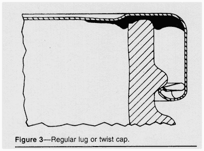
The lug or twist cap (Figure 3) has gained steadily in
popularity to become the predominant vacuum-cap type. It is
referred to as a convenience or utility closure, because it
can be removed without a tool and forms a good reseal for storage.
1. Structural components--The
lug cap consists of a steel shell and may have from three to
six lugs, depending on its diameter; it normally contains a
flowed-in Plastisols gasket.
2. Application and seal formation--The
headspace of the glass container is swept by steam the same
as the other closure styles. Lug caps are secured to the glass
finish. It is desirable, in most instances, that the gasket
be softened by heat in the capper to facilitate sealing. Both
the lugs and vacuum, hold the cap in place on the glass finish,
but vacuum is the most important.
PT (Press-on Twist-off) Cap
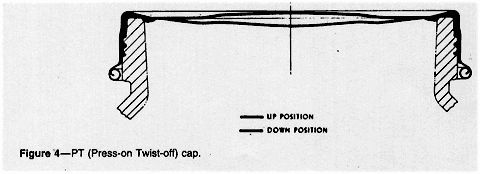
The Press-on Twist-off or PT cap is in
widespread use for baby foods as well as other products (Figure
4). It combines the simple application requirements
of a press-on closure with the convenience of a lug cap:
1. Structural components-The
cap consists of a steel shell that has no lugs. The gasket is
molded Plastisols that covers a sealing area extending from
the outer edge of the top panel to the curl of the cap, forming
the primary top seal and a secondary long side seal. The standard
baby food design contains a safety button or flip panel, as
do most other PT caps.
2. Application and seal formation--Application
requirements call for simply pressing the cap down on the glass
finish after flowing steam over the headspace. The PT closure
gasket must be properly heated prior to application. The glass
threads form impressions in the skirt of the cap gasket that
allow the cap to be cammed-off when twisted open. The PT closure
is help in place on the finish primarily by vacuum with some
assistance from the thread impressions formed in the gasket
wall when the cap is headed then cooled
PLCT
(Plastisols-lined Continuous Thread) Cap
The PLCT cap consists of a metal
shell with a threaded skirt that is knurled. It contains a flowed-in
Plastisols gasket and is applied by screwing the closure onto
the glass finish. The PLCT cap may be used in both steam and
non-steam applications.
CLOSURE
EVALUATION
The two general types of closure inspections
include: (1) visual, non-destructive, external observations
or measurements made at frequent intervals, and (2) cap removal
or destructive tests made at less frequent intervals, because
the integrity of the seal is destroyed. Both of these tests
and observations shall be made at the capper and after processing
and cooling. The appropriate teats and observations for each
type of closure being considered are listed in
Table 1.
|
Table 1
-- Recommended tests and observations of
vacuum closures for glass containers.
|
|
|
|
Type
of closure
|
|
|
|
|
PT
|
Lug
|
PLCT
|
|
AT
CAPPER
|
|
|
|
|
|
Non-Destructive
External Inspection
|
|
|
|
|
|
Cap
Tilt
|
|
Yes
|
|
|
|
Vacuum
(cap panel concavity)
|
|
Yes
|
Yes
|
Yes
|
|
Pull-up
|
|
|
Yes
|
|
|
Cocked
Cap
|
|
|
Yes
|
Yes
|
|
Crushed
lug
|
|
|
Yes
|
|
|
|
|
|
|
|
|
Destructive
Removal Inspection
|
|
|
|
|
|
Cap
Tilt
|
|
|
Yes
|
|
|
Vacuum
(gauge)
|
|
Yes
|
Yes
|
Yes
|
|
Temperature
|
|
Yes
|
Yes
|
Yes
|
|
Headspace
|
|
Yes
|
Yes
|
Yes
|
|
Security
|
|
|
Yes
|
|
|
Gasket
Impression
|
|
|
Yes
|
Yes
|
|
|
|
|
|
|
|
AFTER
PROCESSING AND COOLING
|
|
|
|
|
|
|
|
|
|
|
|
Non-Destructive
External Inspection
|
|
|
|
|
|
Cap
Tilt
|
|
Yes
|
|
|
|
Vacuum
(cap panel concavity)
|
|
Yes
|
Yes
|
Yes
|
|
Pull-up
|
|
|
Yes
|
|
|
Cocked
Cap
|
|
|
Yes
|
Yes
|
|
Crushed
lug
|
|
|
Yes
|
|
|
Button
Position (down)
|
|
Yes
|
Yes
|
Yes
|
|
|
|
|
|
|
|
Destructive
Removal Inspection
|
|
|
|
|
|
Cap
Tilt
|
|
Yes
|
|
|
|
Vacuum
(gauge)
|
|
Yes
|
Yes
|
Yes
|
|
Temperature
|
|
Yes
|
Yes
|
Yes
|
|
Headspace
|
|
Yes
|
Yes
|
Yes
|
|
Security
|
|
|
Yes
|
|
|
Gasket
Impression
|
|
Yes
|
Yes
|
Yes
|
|
Removal
Torque (opt)
|
|
Yes
|
Yes
|
Yes
|
|
Button
Position (up)
|
|
Yes
|
Yes
|
Yes
|
|
|
|
|
|
|
TESTS
and OBSERVATIONS for CLOSURE APPLICATION and DEFECTS
Cap Tilt--PT caps should be essentially
level, not cocked or tilted, and seated well down on the finish.
This is judged in relation to the transfer bead or shoulder
on the glass container and should not exceed 3/32 of an inch.
Cocked Cap (Figure 5)--The
term cocked cap is used for both the lug cap and the PLCT cap.
It is caused by a lug failing to seat under the glass thread.
It occurs on a PLCT cap when the cap and glass threads fail
to properly engage. As a result, the cap is cross threaded and
becomes cocked.
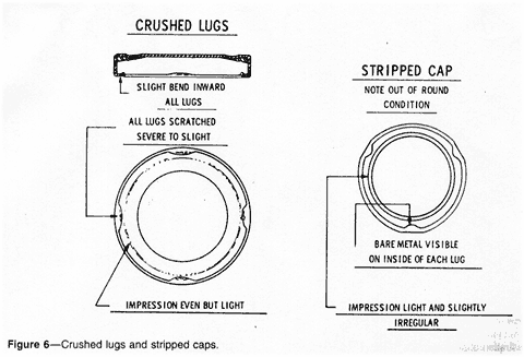
Crushed Lug (Figure 6)--A crushed
lug on a lug cap may be visible on external examination. However,
it may not be readily apparent, since it does not necessarily
result in a tilted cap. It is caused by a lug being forced down
over the glass thread by the capper's sealing mechanism.
Stripped Cap (Figure 6)--A
stripped cap is a lug cap that has been over-applied to the
extent that the lugs have been "stripped" off the
glass threads on the finish. On visual examination, the lugs
appear to be pulled outward.
Vacuum--In most cases, a vacuum
will be formed in the package when it comes out of the capper,
and the panel of the cap will show a concavity or dished-in
appearance indicating the presence of a vacuum.
On PT caps there must be at least five inches of vacuum out
of the capper to avoid loose caps. However, a vacuum button,
if present, may not be down at this point. After processing
and cooling, the button must be down and return to the up position
when the cap is removed.
The exact amount of vacuum present is determined with a vacuum
gauge and should read within the range for the product being
run. This procedure is a destructive test that results in loss
of the package integrity.
Temperature- The product temperature
should be within the normal range for that product being run
and should be recorded in conjunction with vacuum.
Headspace--In most cases, headspace
should be not less than 6 percent of the container volume at
the sealing temperature. Once the relationship of headspace
volume for a specific product is established for a given
container, the headspace may be measured with a depth or headspace
gauge rather than by volume.
Gasket--After cap removal there
should be a visible, even impression in the gasket 360 degrees
around the circumference indicating tight contact with the glass
finish.
Cut-Thru--Cut-thru occurs when the
top of the glass finish has pushed completely through the
gasket on the metal. This problem results in a leaky seal and
requires immediate corrective action.
Removal Torque--Removal torque is
the force required to remove a cap and can be measured on a
standard torque meter. Removal torque should not be used as
a measurement for the proper application of lug-style closures,
but it may be valuable quality control tool for measuring removal
torque trends. Removal torque, however, is used for the measurement
of PLCT cap application. It is suggested that the optimum removal
torque should be one-half the the diameter of the closure. This
is not an absolute rule, and there is flexibility both above
and below the optimum removal torque.
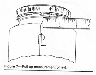
Pull-Up--Pull-up, also known as lug
position, is a nondestructive method of measuring the engagement
of the closure lugs on the threads of the glass finish.
This pull-up or lug position is defined as the distance between
the leading edge of the cap lug and the vertical neck ring seam
on the glass finish. It is measured in 1/16 inch increments.
To measure this position, first find the vertical neck ring
seam on the glass finish. There are two vertical seams on the
glass finish 180 degrees apart.


